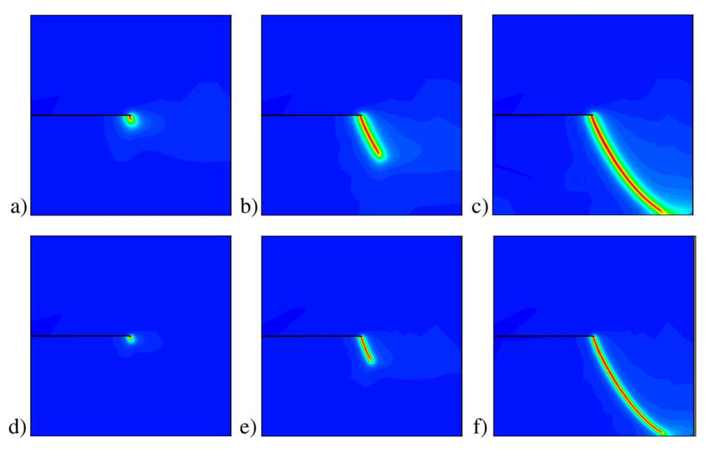
You are applying a Displacement driven loading condition to the top surface, not force/traction driven. You should not always expect similar forces. Additionally when in shear you are loading in the direction of the crack whereas in tension you are loading perpendicular. You are getting shear loading by forcing the top surface to translate to the right through a DirichletBC
Correct. You are accessing that dimension of the VectorFunctionSpace and prescribing a fixed displacement. That is fine.
For the post’s reference @arianaqyp’s original post references the same author but from a different paper.
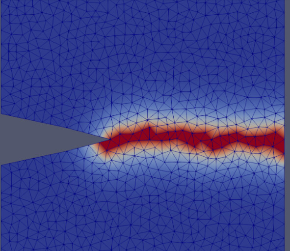
I would check over your code and verify your conditions match the paper. From your graphic above it looks like you should also constrain the vertical displacement on the top surface. Consider specifics such as that.
It’s because the author’s code only generates a .txt file with the force and displacement values, separated by a space. I would like to know how you implemented it in the code to generate the graphs.
@Caio_Cesar sorry for the late reply. I used python to plot the graph. you can read the values in the .txt file and plot it out like how you would for any other graphs. I hope this helps.
I have talked to the creator of the article and he showed me that I can simply eliminate the boundary condition for “Crack” and it would work, like this:
bc_phi=[ ]
He ran the code and it worked, but said I needed to refine the mesh locally (not exactly the same mesh but he just eliminated the Crack).
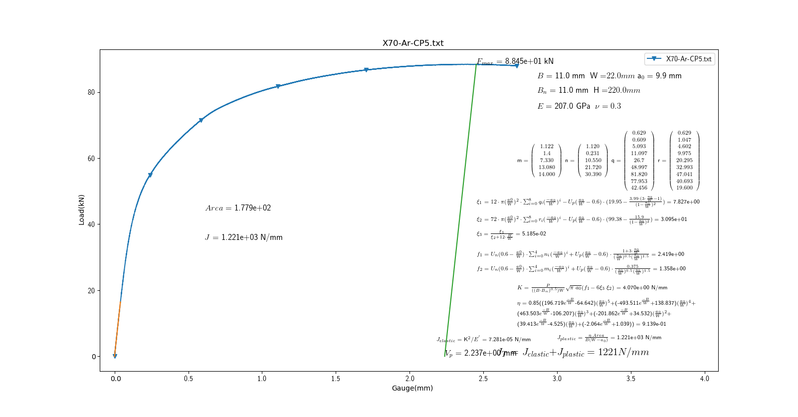
My problem now is with the remote displacement, because I don’t know what value to apply to it according to my problem. The experimental result is this graph of load and displacement
Typically you should try to match your displacement rate (you can take smaller time steps but the rate should match) to that of your experiment. Ideally you know the testing conditions where this data came from. I don’t know what material you are trying to model but you should consider if there are time-dependent and/or irrecoverable mechanisms, it’s clear from your graph the material is ductile. Your J-Integral accounts for both the elastic and plastic energy dissipation. I do not think you can replicate the above data with the purely elastic constitutive model in your code above.
Nevertheless, the force x displacement data is not correct, and I’m thinking if it is because I use a purely elastic constitutive model, or because the remote displacement is incorrect.
@Zhitong
Absolutely, I encourage you to search explicitly for research related to 3D applications of the phase field approach to fracture. For Example. There is nothing in the formulation that constrains it to 2D examples however many practical problems are reduced as such.
Please provide more details about your issue or open a new thread. Include a photo or more explicitly explain the challenge you are experiencing. The community can’t effectively help you with the information you’ve posted.