Problematic mesh causing all-zero rows in the assembled matrix

Gmsh is used to generate extruding geometry and mesh as shown in the attached fig (a, b). I solved Stokes problem on those meshes and got NaN results. The measure in the below link was used to found there exists all-zero rows in the assembled matrices. The corresponding DOFs to the all-zero rows were marked by the rules in green.

I guess it is due to a mixed problem of gmsh and dolfinx, where a type of mesh generated from gmsh cannot be precisely recognized by dolfinx (as correct boundary condition). But I cannot reproduce this problem. Any advice on solving this problem or measures can be taken to diagnose where comes the problem?

I tried to abstract this problem: as the mesh is not fine enough, only a single mesh is distributed on the shape corner, where may not correctly treated as boundary. (?) In my attempt in fig (c), I connected two cubes, where one is slightly larger than the other one, and only one layer of mesh is on the edge. But this mesh works without problem.

I do not understand your description of the problem. If DOLFINx can read the mesh, it should be possible to locate relevant facet tags/markers.
Without the code that produces the mesh and gives you issues with bcs (a minimal reproducible example), it is really hard to say anything about what goes wrong.

As stated before, we need to have a way of looking at the mesh (i.e. a script to reproduce it, its markers etc).

The mesh and code main.py are here: https://drive.google.com/file/d/1haXGCXzKZSS1QlqMUBpGiYLCJEFKqP7x/view?usp=sharing. As the whole mesh is complicated, so the only problematic part is truncated.

Run the code with DOLFINx v0.9.0, yielding 5 DOFs to the all-zero rows as

Found coordinates: dof = np.int32(32), coords[index] = array([ 5976.96870968, -1193.41938619, -3040.        ])
Found coordinates: dof = np.int32(142), coords[index] = array([ 5967.45756383,  -907.49851714, -3040.        ])
Found coordinates: dof = np.int32(701), coords[index] = array([ 5999.11394495,  -705.38      , -3000.        ])
Found coordinates: dof = np.int32(3501), coords[index] = array([ 6318.38,  -687.88, -3040.  ])
Found coordinates: dof = np.int32(11919), coords[index] = array([ 6436.52080859, -1229.05201739, -3000.        ])

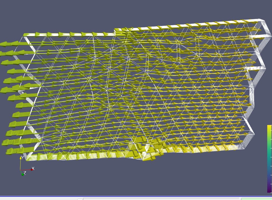
4 of them are from the edges due to mesh truncation, which can be igonred. 1 of them causes the problem in the realistic application, which is marked by the green arrow:

Found coordinates: dof = np.int32(3501), coords[index] = array([ 6318.38,  -687.88, -3040.  ])

MWE (main.py):

import os
os.environ['OMP_NUM_THREADS'] = '1'

import time
from mpi4py import MPI
comm = MPI.COMM_WORLD
rank = comm.rank

import basix, ufl
import numpy as np
from dolfinx import fem, io, mesh
from dolfinx.fem.petsc import LinearProblem

prefix = "./" # CHANGE here to the mesh

comm = MPI.COMM_WORLD
rank = comm.rank
mu = 1
tdim = 3
fdim = tdim - 1
v_order = 2

t0 = time.time()
_mesh = io.XDMFFile(comm, prefix + "truncated.xdmf", "r").read_mesh()

def inlet(x):
    return x[0] < 6050

def outlet(x):
    return x[0] > 6800

V_element = basix.ufl.element("Lagrange", _mesh.basix_cell(), v_order, shape=(tdim,))
Q_element = basix.ufl.element("Lagrange", _mesh.basix_cell(), 1)
W_element = basix.ufl.mixed_element([V_element, Q_element])
W = fem.functionspace(_mesh, W_element)

W0 = W.sub(0)
V = W0.collapse()[0]
W1 = W.sub(1)
Q = W1.collapse()[0]

_mesh.topology.create_connectivity(fdim, tdim)
boundary_facets = mesh.exterior_facet_indices(_mesh.topology)
Gamma_inlet = mesh.locate_entities_boundary(_mesh, fdim, inlet)
Gamma_outlet = mesh.locate_entities_boundary(_mesh, fdim, outlet)

inout = np.concatenate((Gamma_inlet, Gamma_outlet))
Gamma_wall = np.setdiff1d(boundary_facets, inout)

vq = ufl.TestFunction(W)
(v, q) = ufl.split(vq)
dup = ufl.TrialFunction(W)
(du, dp) = ufl.split(dup)
up = fem.Function(W)
(u, p) = ufl.split(up)

F_stokes = ( mu * ufl.inner((2.0*ufl.sym(ufl.nabla_grad(du))), 
                                 ufl.sym(ufl.nabla_grad(v))) * ufl.dx
            - ufl.inner(dp, ufl.div(v)) * ufl.dx
            + ufl.inner(ufl.div(du), q) * ufl.dx
            + ufl.inner(u, v) * ufl.dx)


# Pseudo boundary condition
u_bc = fem.Function(V)
bc_wall = fem.dirichletbc(u_bc, fem.locate_dofs_topological((W0, V), fdim, Gamma_wall), W0)
bc_inlet = fem.dirichletbc(u_bc, fem.locate_dofs_topological((W0, V), fdim, Gamma_inlet), W0)
bcs = [bc_inlet, bc_wall]
a, L = ufl.system(F_stokes)
problem_stokes = LinearProblem(a, L, bcs=bcs, u=up, petsc_options={"ksp_type": "preonly", 
                                                                   "pc_type": "lu", 
                                                                   "pc_factor_mat_solver_type": "mumps"})

problem = problem_stokes
problem._A.zeroEntries()

fem.petsc.assemble_matrix(problem._A, problem._a, bcs=problem.bcs)
problem._A.assemble()

# Get diagonal of assembled A matrix
diagonal = problem._A.getDiagonal()
diagonal_values = diagonal.array

# Get zero rows of assembled A matrix.
zero_rows = problem._A.findZeroRows()
zero_rows_values_global = zero_rows.array
local_start = W.dofmap.index_map.local_range[0] * W.dofmap.index_map_bs

# Maps global numbering to local numbering
zero_rows_values_local = zero_rows_values_global - \
    local_start

# Find the subspaces that contain zero rows
for i in range(W.num_sub_spaces):
    v_sub, sub_to_parent = W.sub(i).collapse()
    
    if len(zero_rows_values_local) > 0:
        coords = v_sub.tabulate_dof_coordinates()
        for dof in zero_rows_values_local:
            if dof in sub_to_parent:
                index = sub_to_parent.index(dof)
                print(f"Found coordinates: {dof = }, {coords[index] = }", flush = True)

This file is under restriction.
Please add the script to the actual post, as google drive links might disappear in the future or get deleted by you.

Still, I don’t quite understand your issue.
Are you saying that when assembly the stokes problem, you get some zero rows for a specific set of dofs, which are not located as boundary dofs of your mesh?

What do you mean here? Add mesh generation script? If so, that is too complicated to put here. I set the link again, and it should be OK to access. Have a look again please:

The DOF are actually located on the boundary. But not sure why wall boundary condition is not applied onto it.

Let’s then simplify the problem a bit to debug it.
Start by looking at the facet markers made by your marking script, i.e.

import os

os.environ["OMP_NUM_THREADS"] = "1"

import time
from mpi4py import MPI

comm = MPI.COMM_WORLD
rank = comm.rank

import basix, ufl
import numpy as np
from dolfinx import fem, io, mesh

prefix = "./"  # CHANGE here to the mesh

comm = MPI.COMM_WORLD
rank = comm.rank
mu = 1
tdim = 3
fdim = tdim - 1
v_order = 2

t0 = time.time()
_mesh = io.XDMFFile(comm, prefix + "truncated.xdmf", "r").read_mesh()


def inlet(x):
    return x[0] < 6050


def outlet(x):
    return x[0] > 6800


V_element = basix.ufl.element("Lagrange", _mesh.basix_cell(), v_order, shape=(tdim,))
Q_element = basix.ufl.element("Lagrange", _mesh.basix_cell(), 1)
W_element = basix.ufl.mixed_element([V_element, Q_element])
W = fem.functionspace(_mesh, W_element)

W0 = W.sub(0)
V = W0.collapse()[0]
W1 = W.sub(1)
Q = W1.collapse()[0]

_mesh.topology.create_connectivity(fdim, tdim)
boundary_facets = mesh.exterior_facet_indices(_mesh.topology)
Gamma_inlet = mesh.locate_entities_boundary(_mesh, fdim, inlet)
Gamma_outlet = mesh.locate_entities_boundary(_mesh, fdim, outlet)

inout = np.concatenate((Gamma_inlet, Gamma_outlet))
Gamma_wall = np.setdiff1d(boundary_facets, inout)

num_facets = _mesh.topology.index_map(fdim).size_local
values = np.zeros(num_facets, dtype=np.int32)
values[Gamma_inlet] = 1
values[Gamma_outlet] = 2
values[Gamma_wall] = 3
facet_tags = mesh.meshtags(_mesh, fdim, np.arange(num_facets, dtype=np.int32), values)
with io.XDMFFile(comm, "truncated_facet_tags.xdmf", "w") as xdmf:
    xdmf.write_mesh(_mesh)
    xdmf.write_meshtags(facet_tags, _mesh.geometry)

which gives the figure

which means that it is being marked with the wall marker.
I.e. the markers are not the issue.
Let’s then move on to the dirichlet condition.
If we look at applying a non-zero value, to ensure that you can check if something get set, add:


u_bc_wall = fem.Function(V)
u_bc_wall.interpolate(lambda x: 0.001 * x)
bc_wall = fem.dirichletbc(
    u_bc_wall, fem.locate_dofs_topological((W0, V), fdim, Gamma_wall), W0
)
u_bc_inlet = fem.Function(V)
u_bc_inlet.interpolate(lambda x: -0.001 * x)
bc_inlet = fem.dirichletbc(
    u_bc_inlet, fem.locate_dofs_topological((W0, V), fdim, Gamma_inlet), W0
)

bcs = [bc_inlet, bc_wall]
w = fem.Function(W)
for bc in bcs:
    bc.set(w.x.array)

w0 = w.sub(0).collapse()
with io.VTXWriter(comm, "truncated_velocity.bp", [w0]) as vtx:
    vtx.write(0.0)

which yields


I.e. the bc is applied.

It is not the BC in itself that is an issue (as the dofs that you are talking about is also in the pressure space, not in the the velocity space, print the subspace index together with the nodes).
In general, we solving problems with P2-P1, you cannot expect well behaved convergence if a cell has all vertices on the boundary, ref: https://epubs.siam.org/doi/abs/10.1137/S0036142994270193
(Theorem 3.1)

THEOREM 3.1. Let {Th} be a regular sequence of decompositions of Ω by means
of tetrahedra. Assume that every element K ∈ Th has at least one internal vertex.
Then the choice of spaces
(3.1) Vh = {v ∈ H1
0(Ω)3 | v|K ∈ Pk+1(K) ∀K ∈ Th},
Qh = {q ∈ H1(Ω) | p|K ∈ Pk ∀K ∈ Th, ∫
Ω q = 0}
satisfies the inf-sup condition (1.6)

This can for instance be fixed with a specific mesh refinement.
I’ve made a script that detects these situations at:

1 Like